Search

Thursday, June 24, 2010

The Millipede

Me and a friend are both trying to build a millipede. Because of obvious reasons, the millipede is NOT going to have 1000 feet!!! Instead, it's going to have 16 pager motors as feet. It will also have 3 MicroMotors to ''bend'' towards light, and a backup sensor.

FEATURES:
16 PagerMotors as feet
3 MicroMotors to seek light
PhotoTrophic
Obstacle avoidance
Looks Cool!!!

MECHANICS:
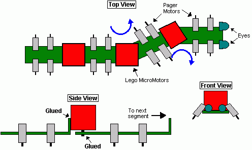
Millipede is divided in four segments. Each segment (except the first one) is glued to a MicroMotor turned upside-down. The motor shaft is then glued to the next segment. Each segment can rotate left/right and has 2 PagerMotors on each side. This way, the millipede should turn towards the most lighted area. I've calculated that the waist motors should turn only 30o-45o every second or so. This means that I will need the motors to be 7-15 rpm. Candidates for this job can be the Lego MicroMotor (http://costaricabeam.solarbotics.net/Info/Lego%20MicroMotor.htm), Solarbotics GM or BabyGM (unless I can get some MU915L Escaps!!!).
Weigth was a major concern since the whole bot was impulsed by pagermotors. The waist motors should weigth no more than 70g and the body (including electronics) is about <100g.>

ELECTRONICS:

Circuit diagram
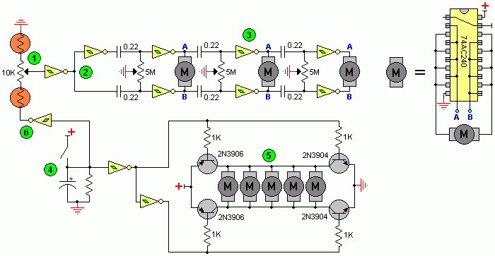
I made up this circuit, as this is my first ''big'' BEAM creation I have no idea if it works properly. The upper 3 Ms are the Lego MicroMotors and the lower Ms should be the 16 PagerMotors. On the right, you can see the MicroMotors driver.

Here is the explanation:
1 This is the voltage divider. It divides voltage depending on which side is more iluminated, then, the schmitt changes the signal from a wave to a straight pulse.
2 The (usual) Nv only works when the input receives a HIGH, and that is the job of the schmitts. If the first schmitt outputs a HIGH the the lower strip of Nvs will work, the upper strip should stay calm because the second schmitt inverts the signal to a LOW. Thanks Math!!!
3 I can now be sure that there won't be 2 pulses on a same motor, and that when the first motor turns left (or right) the next one will also turn that same way, and the next and the next.... Only the first motor is affected by light, the others follow (in a wave pattern) the one before themselves. Since the millipede is moving forward while all this happens, a nice wave should appear when the bot has locked his path towards the light source.
4 This is the backup switch. When the bot bumps into something like... Hmm....anything, the cap is discharged trough the right schmitt. The (now LOW) output of the schmitt will reverse the PagerMotors, thus, reversing the whole bot.
5 This is the PagerMotors driver. I took the 4 transistor circuit design and modified it to be used with only one input signal. I know I won't be able to drive the 16 motors with 2N390X transistors, I used them in the schematic only because I need to find more powerful ones. Probably FETs?
6 As an extra (Yupeee), when the bot reverses it also makes the ''spinal column'' think that light is fully comming only from one direction. Because of this, when the millipede reverses, it also turns to one side all the body.

I still need to order the components (Let's just say there are not many 74**14s or 240s in Costa Rica), so the final version may be different than the drawings. I'm also thinking about using the Baby GMs that Solarbotics sell instead of the Lego MicroMotors. If you can help me with anything about the schematic, just email me.

A circuit diagram

ConceptDraw PRO
Discover the World of Visual Communication©

Wiring Diagrams with ConceptDraw PRO

A wiring diagram is a comprehensive diagram of each electrical circuit system showing all the connectors, wiring, terminal boards, signal connections (buses) between the devices and electrical or electronic components of the circuit. It also identifies the wires by wire numbers or colour coding. Wiring diagrams are necessary to troubleshoot and fix electrical or electronic circuits.

Wiring Diagram

A circuit diagram makes use of standardized symbols that represent electrical components or devices. It is easier to draw these symbols than drawing the concrete pictures of the components.

Wiring Diagram

The actual components might change appearance as the electronics industry revises them or renders them obsolete. The diagrams describe the way in which the components are connected electrically. There are drawn lines that stand for wires or conductors between the appropriate connection points on the symbols; no particular type of wire or physical distance between components is implied; two components might be separated by a few inches or centimeters or a meter or feet.

HOW TO READ CIRCUIT DIAGRAMS

introHOW TO READ CIRCUIT DIAGRAMS

this instructable will show you exactly how to read all those confusing circuit diagrams and then how to assemble the circuits on a breadboard!

for all the electronics hobbyist wannabes this is a MUST-READ instructable.

knowing how to read circuits is a very useful skill that will help you out all the time. especially if you start messing around with building little electronics projects.

In addition to reading this instructable it may be a good idea for you to read my other instructable "electronics components and what they do" to get a good understanding of what you are doing when building a project. (woops not done with this yet, i got caught up with other stuff, check back in a week or so)

Z80


The purpose of this page and its sub pages about members of Z80 family (and close relatives) is to collect and share information and good ideas. I know there are lots of people out there, who have developed some good utilities and hardware solutions. Now we all can share this infomation.
This page contain docs, FAQs, source code, (cross-)assemblers, (cross-)compilers, utilities, etc. as well as links to other Z80 relevant stuff.
Some of the info found here is property of Zilog, like hardware docs, instruction sets, and some of the software available. Read the copyright notice.
If you know an URL matching the subject of this WWW-page, tell me, and give recommendations where to place best.
Some of the links here are no more online and some are not yet correct: they are marked with a ??? sequence; in case you know the appropriate URL: I'm ready for an update.
Please report all updates, corrections and suggestions to the webmaster Gaby Chaudry.
Be aware of the fact that many products mentioned in this series of Z80 related documents are nowadays out of production: if you want to start a project, don't forget to check where to get the parts from, and what the conditions are ...

Emergency Light Circuit Diagram

Emergency Light Circuit Diagram


The circuit of automatic emergency light presented here has the following features: 1. When the mains supply (230V AC) is available, it charges a 12V battery up to 13.5V and then the battery is disconnected from the charging section. 2. When the battery discharges up to 10.2V, it is disconnected from the load and the charging process is resumed. 3. If the mains voltage is available and there is darkness in the room, load (bulb or tube) is turned on by taking power from the mains; otherwise the battery is connected to the load. 4. When the battery discharges up to 10.2V and if the mains is not yet available, the battery is completely disconnected from the circuit to avoid its further discharge. The mains supply of 230V AC is stepped down to 18V AC (RMS) using a 230V AC primary to 0-18V AC, 2A secondary transformer (X1), generally used in 36cm B&W TVs. Diodes D1 through D4 form bridge rectifier and capacitor C5 filters the voltage, providing about 25V DC at the output. Charging section includes 33-ohm, 10-watt resistor R2 which limits the charging current to about 425 mA when battery voltage is about 10.2V, or to 325 mA when battery voltage is about 13.5V. When the battery charges to 13.5V (as set by VR2), zener diode D17 goes into breakdown region, thereby triggering triac TR1. Now, since DC is passing through the triac, it remains continuously ‘on’ even if the gate current is reduced to zero (by disconnecting the gate terminal). Once the battery is fully charged, charging section is cut-off from the battery due to energisation of relay RL2. This relay remains ‘on’ even if the power fails because of connection to the battery via diode D10. S4, a normally closed switch, is included to manually restart the charging process if required. Battery disconnect and charging restart section comprises an NE555 timer (IC2) wired in monostable mode. When the battery voltage is above 10.2V (as indicated by red LED D15), zener diode (D16) remains in the breakdown region, making the trigger pin 2 of IC2 high, thereby maintaining output pin 3 in low voltage state. Thus, relay RL3 is ‘on’ and relay RL4 is ‘off.’ But as soon as the battery voltage falls to about 10.2V (as set by preset VR1), zener diode D16 comes out of conduction, making pin 2 low and pin 3 high to turn ‘on’ relay RL4 and orange LED D13. This also switches off relay RL3 and LED D15. Now, if the mains is available, charging restarts due to de-energisation of relay RL2 because when relay RL4 is ‘on,’ it breaks the circuit of relay RL2 and triac TR1. But if the mains supply is not present, both relays RL3 and RL1 de-energise, disconnecting the battery from the remaining circuit. Thus when battery voltage falls to 10.2 volts, its further discharge is eliminated. But as soon as the mains supply resumes, it energises relay RL1, thereby connecting the battery again to the circuit. Light sensor section also makes use of a 555 timer IC in the monostable mode. As long as normal light is falling on LDR1, its resistance is comparatively low. As a result pin 2 of IC3 is held near Vcc and its output at pin 3 is at low level. In darkness, LDR resistance is very high, which causes pin 2 of IC3 to fall to near ground potential and thus trigger it. As a consequence, output pin 3 goes high during the monostable pulse period, forward biasing transistor T3 which goes into saturation, energising relay RL5. With auto/bypass switch S2 off (in auto mode), the load gets connected to supply via switch S3. If desired, the load may be switched during the day-time by flipping switch S2 to ‘on’ position (manual). Preset VR3 is the sensitivity control used for setting threshold light level at which the load is to be automatically switched on/off. Capacitors with the relays ensure that there is no chattering of the relays. When the mains is present, diode D8 couples the input voltage to regulator IC1 whereas diode D10 feeds the input voltage to it (from battery) in absense of mains supply. Diode D5 connects the load to the power supply section via resistor R5 when mains is available (diode D18 does not conduct). However, when mains power fails, the situation reverses and diode D18 conducts while diode D5 does not conduct. . The load can be any bulb of 12 volts with a maximum current rating of 2 amperes (24 watts). Resistor R5 is supposed to drop approximately 12 volts when the load current flows through it during mains availability . Hence power dissipated in it would almost be equal to the load power. It is therefore desirable to replace R5 with a bulb of similar voltage and wattage as the load so that during mains availability we have more (double) light than when the load is fed from the battery. For setting presets VR1 and VR2, just take out (desolder one end) diodes D7, D10 and D18. Connect a variable source of power supply in place of battery. Set preset VR1 so that battery-high LED D15 is just off at 10.2V of the variable source. Increase the potential of the variable source and observe the shift from LO BAT LED D13 to D15. Now make the voltage of the source 13.5V and set preset VR2 so that relay RL2 just energises. Then decrease the voltage slowly and observe that relay RL2 does not de-energise above 10.2V. At 10.2V, LED D15 should be off and relay RL2 should de-energise while LED D13 should light up. Preset VR3 can be adjusted during evening hours so that the load is ‘on’ during the desired light conditions

Emergency Light Circuit Diagram

Circuit diagram for emergency light which automatically switches on when power supply fails and automatically shuts down when power supply resumes


18W Audio Amplifier

circuit diagram

Amplifier parts:
P1 = 22K Log.Potentiometer (Dual-gang for stereo)
R1 = 1K 1/4W Resistor
R2 = 4K7 1/4W Resistor
R3 = 100R 1/4W Resistor
R4 = 4K7 1/4W Resistor
R5 = 82K 1/4W Resistor
R6 = 10R 1/2W Resistor
R7 = R22 4W Resistor (wire wound)
R8 = 1K 1/2W Trimmer Cermet (optional)
C1 = 470nF 63V Polyester Capacitor
C2,C5 = 100uF 3V Tantalum bead Capacitors
C3,C4 = 470uF 25V Electrolytic Capacitors
C6 = 100nF 63V Polyester Capacitor
D1 = 1N4148 75V 150mA Diode
IC1 = TLE2141C Low noise,high voltage,high slew-rate Op-amp
Q1 = BC182 50V 100mA NPN Transistor
Q2 = BC212 50V 100mA PNP Transistor
Q3 = TIP42A 60V 6A PNP Transistor
Q4 = TIP41A 60V 6A NPN Transistor
J1 RCA audio input socket

Power supply parts:
R9 = 2K2 1/4W Resistor
C7,C8 = 4700uF 25V Electrolytic Capacitors
D2 100V 4A Diode bridge
D3 5mm. Red LED
T1 220V Primary, 15 + 15V Secondary 50VA Mains transformer
PL1 Male Mains plug
SW1 SPST Mains switch

Notes:
Can be directly connected to CD players, tuners and tape recorders.
Don't exceed 23 + 23V supply.
Q3 and Q4 must be mounted on heat sink.
D1 must be in thermal contact with Q1.
Quiescent current (best measured with an Avo-meter in series with Q3 Emitter) is not critical.
Adjust R3 to read a current between 20 to 30 mA with no input signal.
To facilitate current setting add R8 (optional).
A correct grounding is very important to eliminate hum and ground loops. Connect in the same point the ground sides of J1, P1, C2, C3 &C4. Connect C6 at the output ground.
Then connect separately the input and output grounds at the power supply ground.

Technical data:
Output power: 18 Watt RMS @ 8 Ohm (1KHz sine wave)
Sensitivity: 150mV input for 18W output
Frequency response: 30Hz to 20KHz -1dB
Total harmonic distortion @ 1KHz: 0.1W 0.02% 1W 0.01% 5W 0.01% 10W 0.03%
Total harmonic distortion @10KHz: 0.1W 0.04% 1W 0.05% 5W 0.06% 10W 0.15%
Unconditionally stable on capacitive loads


desing1