


Warning:
The use of this device is forbidden to Pace-Maker bearers and pregnant women. Don't place the electrodes on cuts, wounds, injuries or varices. Obviously we can't claim or prove any therapeutic effectiveness for this device.
Parts:
P1______________4K7 Linear Potentiometer
R1____________180K 1/4W Resistor
R2______________1K8 1/4W Resistor (see Notes)
R3______________2K2 1/4W Resistor
R4____________100R 1/4W Resistor
C1____________100nF 63V Polyester Capacitor
C2____________100΅F 25V Electrolytic Capacitor
D1______________LED Red 5mm.
D2___________1N4007 1000V 1A Diode
Q1,Q2_________BC327 45V 800mA PNP Transistors
IC1____________7555 or TS555CN CMos Timer IC
T1_____________220V Primary, 12V Secondary 1.2VA Mains transformer (see Notes)
SW1____________SPST Switch (Ganged with P1)
B1_____________3V Battery (two 1.5V AA or AAA cells in series etc.)
Device purpose:
This is a small, portable set, designed for those aiming at look improvement. The Bio-Stimulator provides muscles' stimulation and invigoration but, mainly, it's an aid in removing cellulitis. Tape the electrodes to the skin at both ends of the chosen muscle and rotate P1 knob slowly until a light itch sensation is perceived. Each session should last about 30 - 40 minutes.
Circuit operation:
IC1 generates 150΅Sec. pulses at about 80Hz frequency. Q1 acts as a buffer and Q2 inverts the pulses' polarity and drives the Transformer. Output pulses' amplitude is set by P1 and approximately displayed by LED D1 brightness. D2 protects Q2 against high voltage peaks generated by T1 inductance during switching.
Notes:
* T1 is a small mains transformer 220 to 12V @ 100 or 150mA. It must be reverse connected i.e.: the 12V secondary winding to Q2 Collector and ground, and the 220V primary winding to output electrodes.
* Output voltage is about 60V positive and 150V negative but output current is so small that there is no electric-shock danger.
* In any case P1 should be operated by the "patient", starting with the knob fully counter-clockwise, then rotating it slowly clockwise until the LED starts to illuminate. Stop rotating the knob when a light itch sensation is perceived.
* Best knob position is usually near the center of its range.
* In some cases a greater pulse duration can be more effective in cellulitis treatment. Try changing R2 to 5K6 or 10K maximum: stronger pulses will be easily perceived and the LED will shine more brightly.
* Electrodes can be obtained by small metal plates connected to the circuit's output via usual electric wire and can be taped to the skin. In some cases, moistening them with little water has proven useful.
* SW1 should be ganged to P1 to avoid abrupt voltage peaks on the "patient's" body at switch-on, but a stand alone SPST switch works quite well, provided you remember to set P1 knob fully counter-clockwise at switch-on.
* Current drawing of this circuit is about 1mA @ 3V DC.
* Some commercial sets have four, six or eight output electrodes. To obtain this you can retain the part of the circuit comprising IC1, R1, R2, C1, C2, SW1 and B1. Other parts in the diagram (i.e. P1, R3, R4, D1, D2, Q2 & T1) can be doubled, trebled or quadrupled. Added potentiometers and R3 series resistors must be wired in parallel and all connected from Emitter of Q1 to positive supply.
| Hello to all my readers. Welcome to the latest of the bi-weekly Public Newsletters. – At least, it’s the latest until the next one’s published. Getting a good-looking date The first thing I’m going to tell you in this Newsletter is why I always write the date, online, as above in the title: - It’s all because of Americans. who make up around 1/4 to 1/3rd (0.25 to 0.34) of my readership. As you probably already know; Americans write the date differently compared to we Brits: Where an American would write the date above as 10.23.2009 Brits would write it as 23.10.2009 From the above it seems fairly obvious, provided that you are aware that they’re both the same day, that one is the date written by an American, and one is the date written by a Brit; particularly if you know that it’s the date related to an article published on 23rd October: There’s really no issue there; until it comes to a date like 08.09.2009, or 10.11.2010: One of those dates was written by an American, but which one? - So rather than cause any confusion by writing the date as 08.09.2009; which to an American is 9th August, yet to a Brit is 8th September, I write it out so that it can be understood whichever way round you do it in your part of the world. “Surely everybody knows what month it is!” You retort. Currently yes; but imagine you’re an American digging through archives, finding the post you’re looking for by date, loading it onto a USB stuck, driving to your next destination, and then finding that the post was written by a Brit and that you got the wrong post because you read the date in American format rather than British format. Blog Contents Page Next; I’ve automated the Blog Contents page: In doing so I’ve lost a number of the listings. Everything related to that is explained near the top of that page itself; but I’ll reproduce the important parts here also: - “Previously I was hard-coding each post into the list manually. I actually devised a way of doing it fairly quickly and with little effort. – I just wasn’t happy with doing things that way though: It was something else that had to be done, costing more time, and I also didn’t always remember to do it after every post’s publication. It is in the light of the above that I’ve configured an existing script to handle the matter of posting and updating this Blog Contents page. While the operation is almost perfect, the script is unable to handle [all the previously viewable entries in the list.] …I’ve just done the best I can for now. …Approximately 7 months of posts are currently listed, in total. I’m seeking a solution that will allow me to list more posts: Please bear with me until that time.” Changes to the Welcome Page As you may have noticed, I’ve partially automated the Welcome Page by adding a display of a snippet of my latest post to the page, as well as adding a clickable listings link to any of the latest 20 posts. I’ve also amended and partially rewritten the “Objective of This Blog” text section, in addition to which I’ve made all fonts on the page Trebuchet MS, and all linked text is now standard-link-blue (0000FF hex value.). Reduced input As I stated in the last Public Newsletter, I might yet have to reign back on the frequency with which I post articles at some point. It’s not that I don’t like writing; it’s just that I don’t have a lot of time some days or weeks. If there’s no content added to this blog one day, don’t instantly assume that it’s died. – Anyway, I currently announce future content on the welcome Page, previous to publication, so I’ll announce any gaps too, or simply won’t announce when there’ll be no new material. – If it’s not announced then it won’t happen. Yes I do hand-code that announcement; although if anybody knows of a plugin which will list articles scheduled for publication then I’d be most happy to know about it myself. – With WordPress there’s normally a plugin for it, whatever it is. – It’s just a matter of finding it. I’m going to be producing a different type of content as well as free articles from this coming Monday onwards; that being paid-for premium content, which will be on sale in due course: Yes I’m beginning to step up a gear with monetising this blog. – Well something’s got to pay the rent. As a result I’ll be unable to produce as many articles as I have recently been doing – I just don’t have an unlimited amount of time on my hands. I can probably still produce a few per week for the forseeable future; but if you have something technical and factual that you’d like to post on this blog; be my guest, literally: Submit your prospective guest-posts in line with the contest Can Your Post Make it to The Number One Slot? You never know; you might win. |

And for all those poor souls having just found their first Tek and unsure on how to proceed, finding the poor thing dead and not having a manual, I have here some useful bits of circuit diagram. These I copied from the Tek 585A manual, but I believe them to be reasonably representative of most 530, 540 and 580 series scopes. You may wish to disagree, please let me know. Note: Tube numbers for the non-A versions are different.
Here is something similar for the 560 series of scopes. The diagrams are from the manual of the 564, but I suspect the 561 will be largely identical. I don't know about the 560 itself. The 564B is different.
Notes: See above.
 Kindly offered to the ham community as freeware, the K8 keyer by K1EL is an iambic keyer, embedded as software in a PIC chip. Its biggest advantages are that it is free (duh!), easy to build and very small.
The best implementation I have seen so far, is from W0PWE. He has circuit diagrams, PCB layouts and much more. The original presentation of this keyer can be found at K1EL’s homepage. You will need a PIC programmer to upload the software. I have one available on my Electronics pages.
The disk with the holes you see on the front of my memory keyer is in fact a small speaker that I salvaged from a set of defective cheap headphones. I found that piezzo speakers only give moderate output at the 800Hz the PIC puts out. I must say the headphones speaker doesn’t do any better, but it’s enough because my rig puts out a sidetone as well, and I have my headphones on anyway…
I run the keyer on a pair of AA batteries, which works very well. The keyer does not need an on/off switch, since the idle current of the PIC is only a few µA’s. I haven’t had to replace the batteries for two years.
Me and a friend are both trying to build a millipede. Because of obvious reasons, the millipede is NOT going to have 1000 feet!!! Instead, it's going to have 16 pager motors as feet. It will also have 3 MicroMotors to ''bend'' towards light, and a backup sensor.
FEATURES:
16 PagerMotors as feet
3 MicroMotors to seek light
PhotoTrophic
Obstacle avoidance
Looks Cool!!!
MECHANICS:
Millipede is divided in four segments. Each segment (except the first one) is glued to a MicroMotor turned upside-down. The motor shaft is then glued to the next segment. Each segment can rotate left/right and has 2 PagerMotors on each side. This way, the millipede should turn towards the most lighted area. I've calculated that the waist motors should turn only 30o-45o every second or so. This means that I will need the motors to be 7-15 rpm. Candidates for this job can be the Lego MicroMotor (http://costaricabeam.solarbotics.net/Info/Lego%20MicroMotor.htm), Solarbotics GM or BabyGM (unless I can get some MU915L Escaps!!!).
Weigth was a major concern since the whole bot was impulsed by pagermotors. The waist motors should weigth no more than 70g and the body (including electronics) is about <100g.>
ELECTRONICS:
Circuit diagram
I made up this circuit, as this is my first ''big'' BEAM creation I have no idea if it works properly. The upper 3 Ms are the Lego MicroMotors and the lower Ms should be the 16 PagerMotors. On the right, you can see the MicroMotors driver.
Here is the explanation:
1 This is the voltage divider. It divides voltage depending on which side is more iluminated, then, the schmitt changes the signal from a wave to a straight pulse.
2 The (usual) Nv only works when the input receives a HIGH, and that is the job of the schmitts. If the first schmitt outputs a HIGH the the lower strip of Nvs will work, the upper strip should stay calm because the second schmitt inverts the signal to a LOW. Thanks Math!!!
3 I can now be sure that there won't be 2 pulses on a same motor, and that when the first motor turns left (or right) the next one will also turn that same way, and the next and the next.... Only the first motor is affected by light, the others follow (in a wave pattern) the one before themselves. Since the millipede is moving forward while all this happens, a nice wave should appear when the bot has locked his path towards the light source.
4 This is the backup switch. When the bot bumps into something like... Hmm....anything, the cap is discharged trough the right schmitt. The (now LOW) output of the schmitt will reverse the PagerMotors, thus, reversing the whole bot.
5 This is the PagerMotors driver. I took the 4 transistor circuit design and modified it to be used with only one input signal. I know I won't be able to drive the 16 motors with 2N390X transistors, I used them in the schematic only because I need to find more powerful ones. Probably FETs?
6 As an extra (Yupeee), when the bot reverses it also makes the ''spinal column'' think that light is fully comming only from one direction. Because of this, when the millipede reverses, it also turns to one side all the body.
I still need to order the components (Let's just say there are not many 74**14s or 240s in Costa Rica), so the final version may be different than the drawings. I'm also thinking about using the Baby GMs that Solarbotics sell instead of the Lego MicroMotors. If you can help me with anything about the schematic, just email me.
| ConceptDraw PRO Discover the World of Visual Communication© Wiring Diagrams with ConceptDraw PRO |
A wiring diagram is a comprehensive diagram of each electrical circuit system showing all the connectors, wiring, terminal boards, signal connections (buses) between the devices and electrical or electronic components of the circuit. It also identifies the wires by wire numbers or colour coding. Wiring diagrams are necessary to troubleshoot and fix electrical or electronic circuits.

A circuit diagram makes use of standardized symbols that represent electrical components or devices. It is easier to draw these symbols than drawing the concrete pictures of the components.

The actual components might change appearance as the electronics industry revises them or renders them obsolete. The diagrams describe the way in which the components are connected electrically. There are drawn lines that stand for wires or conductors between the appropriate connection points on the symbols; no particular type of wire or physical distance between components is implied; two components might be separated by a few inches or centimeters or a meter or feet.

The circuit of automatic emergency light presented here has the following features: 1. When the mains supply (230V AC) is available, it charges a 12V battery up to 13.5V and then the battery is disconnected from the charging section. 2. When the battery discharges up to 10.2V, it is disconnected from the load and the charging process is resumed. 3. If the mains voltage is available and there is darkness in the room, load (bulb or tube) is turned on by taking power from the mains; otherwise the battery is connected to the load. 4. When the battery discharges up to 10.2V and if the mains is not yet available, the battery is completely disconnected from the circuit to avoid its further discharge. The mains supply of 230V AC is stepped down to 18V AC (RMS) using a 230V AC primary to 0-18V AC, 2A secondary transformer (X1), generally used in 36cm B&W TVs. Diodes D1 through D4 form bridge rectifier and capacitor C5 filters the voltage, providing about 25V DC at the output. Charging section includes 33-ohm, 10-watt resistor R2 which limits the charging current to about 425 mA when battery voltage is about 10.2V, or to 325 mA when battery voltage is about 13.5V. When the battery charges to 13.5V (as set by VR2), zener diode D17 goes into breakdown region, thereby triggering triac TR1. Now, since DC is passing through the triac, it remains continuously ‘on’ even if the gate current is reduced to zero (by disconnecting the gate terminal). Once the battery is fully charged, charging section is cut-off from the battery due to energisation of relay RL2. This relay remains ‘on’ even if the power fails because of connection to the battery via diode D10. S4, a normally closed switch, is included to manually restart the charging process if required. Battery disconnect and charging restart section comprises an NE555 timer (IC2) wired in monostable mode. When the battery voltage is above 10.2V (as indicated by red LED D15), zener diode (D16) remains in the breakdown region, making the trigger pin 2 of IC2 high, thereby maintaining output pin 3 in low voltage state. Thus, relay RL3 is ‘on’ and relay RL4 is ‘off.’ But as soon as the battery voltage falls to about 10.2V (as set by preset VR1), zener diode D16 comes out of conduction, making pin 2 low and pin 3 high to turn ‘on’ relay RL4 and orange LED D13. This also switches off relay RL3 and LED D15. Now, if the mains is available, charging restarts due to de-energisation of relay RL2 because when relay RL4 is ‘on,’ it breaks the circuit of relay RL2 and triac TR1. But if the mains supply is not present, both relays RL3 and RL1 de-energise, disconnecting the battery from the remaining circuit. Thus when battery voltage falls to 10.2 volts, its further discharge is eliminated. But as soon as the mains supply resumes, it energises relay RL1, thereby connecting the battery again to the circuit. Light sensor section also makes use of a 555 timer IC in the monostable mode. As long as normal light is falling on LDR1, its resistance is comparatively low. As a result pin 2 of IC3 is held near Vcc and its output at pin 3 is at low level. In darkness, LDR resistance is very high, which causes pin 2 of IC3 to fall to near ground potential and thus trigger it. As a consequence, output pin 3 goes high during the monostable pulse period, forward biasing transistor T3 which goes into saturation, energising relay RL5. With auto/bypass switch S2 off (in auto mode), the load gets connected to supply via switch S3. If desired, the load may be switched during the day-time by flipping switch S2 to ‘on’ position (manual). Preset VR3 is the sensitivity control used for setting threshold light level at which the load is to be automatically switched on/off. Capacitors with the relays ensure that there is no chattering of the relays. When the mains is present, diode D8 couples the input voltage to regulator IC1 whereas diode D10 feeds the input voltage to it (from battery) in absense of mains supply. Diode D5 connects the load to the power supply section via resistor R5 when mains is available (diode D18 does not conduct). However, when mains power fails, the situation reverses and diode D18 conducts while diode D5 does not conduct. . The load can be any bulb of 12 volts with a maximum current rating of 2 amperes (24 watts). Resistor R5 is supposed to drop approximately 12 volts when the load current flows through it during mains availability . Hence power dissipated in it would almost be equal to the load power. It is therefore desirable to replace R5 with a bulb of similar voltage and wattage as the load so that during mains availability we have more (double) light than when the load is fed from the battery. For setting presets VR1 and VR2, just take out (desolder one end) diodes D7, D10 and D18. Connect a variable source of power supply in place of battery. Set preset VR1 so that battery-high LED D15 is just off at 10.2V of the variable source. Increase the potential of the variable source and observe the shift from LO BAT LED D13 to D15. Now make the voltage of the source 13.5V and set preset VR2 so that relay RL2 just energises. Then decrease the voltage slowly and observe that relay RL2 does not de-energise above 10.2V. At 10.2V, LED D15 should be off and relay RL2 should de-energise while LED D13 should light up. Preset VR3 can be adjusted during evening hours so that the load is ‘on’ during the desired light conditions
Emergency Light Circuit Diagram

circuit diagram
Amplifier parts:
P1 = 22K Log.Potentiometer (Dual-gang for stereo)
R1 = 1K 1/4W Resistor
R2 = 4K7 1/4W Resistor
R3 = 100R 1/4W Resistor
R4 = 4K7 1/4W Resistor
R5 = 82K 1/4W Resistor
R6 = 10R 1/2W Resistor
R7 = R22 4W Resistor (wire wound)
R8 = 1K 1/2W Trimmer Cermet (optional)
C1 = 470nF 63V Polyester Capacitor
C2,C5 = 100uF 3V Tantalum bead Capacitors
C3,C4 = 470uF 25V Electrolytic Capacitors
C6 = 100nF 63V Polyester Capacitor
D1 = 1N4148 75V 150mA Diode
IC1 = TLE2141C Low noise,high voltage,high slew-rate Op-amp
Q1 = BC182 50V 100mA NPN Transistor
Q2 = BC212 50V 100mA PNP Transistor
Q3 = TIP42A 60V 6A PNP Transistor
Q4 = TIP41A 60V 6A NPN Transistor
J1 RCA audio input socket
Power supply parts:
R9 = 2K2 1/4W Resistor
C7,C8 = 4700uF 25V Electrolytic Capacitors
D2 100V 4A Diode bridge
D3 5mm. Red LED
T1 220V Primary, 15 + 15V Secondary 50VA Mains transformer
PL1 Male Mains plug
SW1 SPST Mains switch
Notes:
Can be directly connected to CD players, tuners and tape recorders.
Don't exceed 23 + 23V supply.
Q3 and Q4 must be mounted on heat sink.
D1 must be in thermal contact with Q1.
Quiescent current (best measured with an Avo-meter in series with Q3 Emitter) is not critical.
Adjust R3 to read a current between 20 to 30 mA with no input signal.
To facilitate current setting add R8 (optional).
A correct grounding is very important to eliminate hum and ground loops. Connect in the same point the ground sides of J1, P1, C2, C3 &C4. Connect C6 at the output ground.
Then connect separately the input and output grounds at the power supply ground.
Technical data:
Output power: 18 Watt RMS @ 8 Ohm (1KHz sine wave)
Sensitivity: 150mV input for 18W output
Frequency response: 30Hz to 20KHz -1dB
Total harmonic distortion @ 1KHz: 0.1W 0.02% 1W 0.01% 5W 0.01% 10W 0.03%
Total harmonic distortion @10KHz: 0.1W 0.04% 1W 0.05% 5W 0.06% 10W 0.15%
Unconditionally stable on capacitive loads
this is a new design of a tutorial board based on the popular PIC16F84A microcontroller. It features eight single leds, a 7-segment display, an LCD display and five push buttons. It is an ideal solution for the beginner to take his/her first programming steps in the world of microcontrollers. Having an in-circuit-programming (ICP) header, it can be easily reprogrammed without unplugging the microcontroller each time, provided that the programmer also supports this feature (like OziPic’er).
Circuit diagram
Connections
PIC16F84A......................Feature
RA0................................JP2 - S3 – JP4
RA1................................JP2 - S4 – JP4
RA2................................JP2 - S5 - JP4
RA3................................JP2 - S6 - JP4
RA4................................JP2 - JP4
PIC16F84A.......................Feature
RB0.........................JP2 – LED1 – 7 Seg (dp) – S7 Debounce - Buzzer
RB1.........................JP2 – LED2– 7 Seg (a) – LCD RS
RB2.........................JP2 – LED3– 7 Seg (b) – LCD R/W
RB3.........................JP2 – LED4– 7 Seg (c) – LCD E
RB4.........................JP2 – LED5– 7 Seg (d) – LCD DB4
RB5.........................JP2 – LED6– 7 Seg (e) – LCD DB5
RB6.........................JP2 – LED7– 7 Seg (f) – LCD DB6
RB7.........................JP2 – LED8– 7 Seg (g) – LCD DB7

Feature Description
- S1 switches the board on and off. When on, the indicator led LED9 is lit.
- S2 resets the microcontroller.
- S8 switches the LCD display on and off
- S9 switches the eight individual leds AND the 7-segment display on and off.
- Push buttons S3 to S6 correspond to RA0-RA3 inputs. They are enabled or disabled by the SW2 dip switch.
- The SW1 dip switch enables or disables the following features :
1. Connects RB0 (used as output) to LED1.
2. Connects RB0 (used as interrupt input) to S7.
3. Enables the debouncing circuit for interrupt switch S7.
4. Connects RB0 (used as output) to the buzzer.
This dip switch must be either 1000 or 0100 or 0110 or 0001.
- The 7-segment display is always connected to the individual leds. Its seven segments correspond to LED2 to LED8 (RB1 to RB7) and the decimal dot to LED1 (RB0). This correspondence enables the 7-segment display to work together with the interrupt switch S7, which is connected to RB0.
- JP4 is an 6-screw external input connector for RA0-RA4. When used, the corresponding input switches S3-S6 must be turned off by SW2. Last screw is ground.
- JP2 is a 14 pin test terminal. A voltmeter or logic analyzer can be connected any time to monitor the signal traffic in the circuit. Last pin is ground.
- JP1 is the ICP header. When in-circuit-programming is performed, the board must be OFF (by S1), as well as the LCD (by S8) and leds (by S9).
- JP3 is a 14-pin connector for the LCD module. Contrast can be adjusted by trimmer R21.
- The board can be powered either by a 9V battery or a 6-12 V power supply.
PDF versions of the schematic and PCB are included. The board has been sucessfully build and it is depicted on the following
photos :
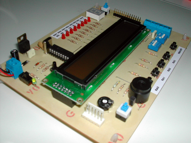

The top photo shows the in-circuit-programming procedure with the help of an appropriate programmer (like OziPic'er) which features an ICP header. In order for the procedure to work correctly, the LCD module has to be disconnected from its socket during programming.
Any futher ideas, comments and corrections are mostly welcome to billy@ee.auth.gr
![]()
![]()

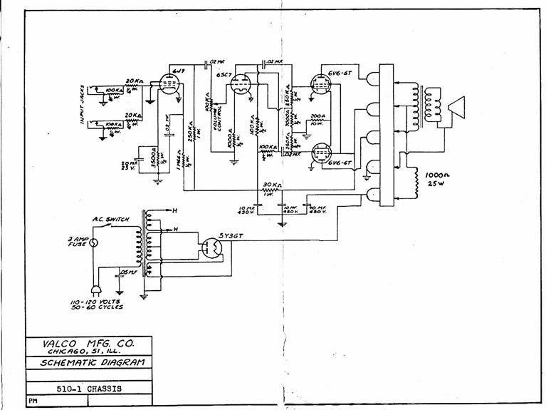
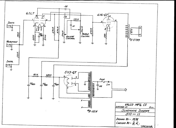
This circuit is very similar to all small amps, (no tone control, 5Watts output and 8"speaker of the 40s, 50s and 60's, such as the National 'Studio 10' (1965) and 'Westwood 1201E (1959)'.
![]()

![]()

Activity 2: Circuit diagrams | ||||
When electricity flows through a circuit it can be used to light up a globe or make an electric motor work. A circuit diagram is used to show you which parts make up the circuit and in what order. Can you connect up circuits using a diagram with symbols as your guide? What to use Batteries, globes, switch, wires, ammeter, electric motor. What to do
| ||||
|
Next Page: Circuit Symbols
Also see: Block Diagrams
 Circuit diagrams show how electronic components are connected together. Each component is represented by a symbol and a few are shown here, for other symbols please see the Circuit Symbols page.

The circuit diagram and stripboard layout for the Adjustable Timer project are shown here so you can see the difference.
A circuit diagram is useful when testing a circuit and for understanding how it works. This is why the instructions for projects include a circuit diagram as well as the stripboard or printed circuit board layout which you need to build the circuit.

Follow these tips for best results:
Circuit diagrams for science are traditionally drawn with the battery or power supply at the top. This is not wrong, but there is usually no advantage in drawing them this way and I think it is less helpful for understanding the circuit.
I suggest that you always draw your circuit diagrams the 'electronics way', even for science!
[I hope your science teacher won't mind too much!]
Note that the negative supply is usually called 0V (zero volts).
This is explained on the Voltage and Current page.
This Christmas Star Circuit Diagram can be used to construct an attractive Christmas Star. When we switch on this circuit, the brightness of lamp L1 gradually increases. When it reaches the maximum brightness level, the brightness starts decreasing gradually. And when it reaches the minimum brightness level, it again increases automatically. This cycle repeats. The increase and decrease of brightness of bulb L1 depends on the charging and discharging of capacitor C3. When the output of IC1 is high, capacitor C3 starts discharging and consequently the brightness of lamp L1 decreases. IC2 is an opto-isolator whereas IC1 is configured as an astable multivibrator. The frequency of IC1 can be changed by varying the value of resistor R2 or the value of capacitor C1. Remember that when you vary the frequency of IC1, you should also vary the values of resistors R3 and R4 correspondingly for better performance. The minimum brightness level of lamp L1 can be changed by adjusting potentiometer VR1. If the brightness of the lamp L1 does not reach a reasonable brightness level, or if the lamp seems to remain in maximum brightness level (watch for a minute), increase the in-circuit resistance of potmeter VR1. If in-circuit resistance of potmeter VR1 is too high, the lamp may flicker in its minimum brightness region, or the lamp may remain in ‘off’ state for a long time. In such cases, decrease the resistance of potmeter VR1 till the brightness of lamp L1 smoothly increases and decreases. When supply voltage varies, you have to adjust potmeter VR1 as stated above, for proper performance of the circuit. A triac such as BT136 can be used in place of the SCR in this circuit. Caution: While adjusting potmeter VR1, care should be taken to avoid electrical shock
Christmas Star Circuit Diagram

Description
Using switch S3 also allows manual control, allowing for curtains to be left only partially open or closed. The circuit controls a motor which is attached to a simple pulley mechanism, to move the curtains. I first started this circuit over 20 years ago and apart from now using metal gears, very little has changed.
Notes:
Automatic Operation
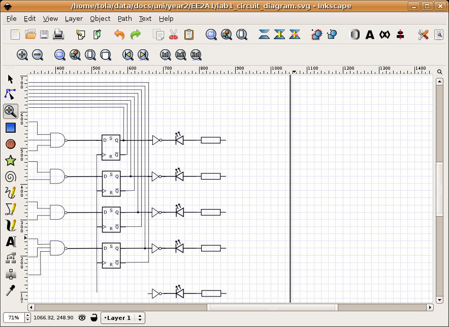
The circuit can be broken down into three main parts; a bistable latch, a timer and a reversing circuit. Toggle switch S3 determines manual or automatic mode. The circuit as shown above is drawn in the automatic position and operation is as follows. The bistable is built around Q1 and Q2 and associated circuitry and controls relay A/2. S1 is used to open the curtains and S2 to close the curtains. At power on, a brief positive pulse is applied to the base of Q2 via C2. Q2 will be on, and activate relay A/2.
The network of C3 and R4 form a low current holding circuit for the relay. Relay A/2 is a 12V relay with a 500 ohm coil. It requires slightly less current to keep a relay energized than it does to operate it. Once the relay has operated, the current through the coil is reduced by R4, saving power consumption. When Q2 is off, C3 will be discharged, but when Q2 becomes active (either at switch on or by pressing S1) capacitor C3 will charge very quickly via the relay coil. The initial charging current is sufficient to energize the relay and current flow through R4 sufficient to keep it energized.
Q1 bias is applied via R3 which is tied to Q2 collector. As Q2 is on, the collector voltage will be low, close to 0v and therefore Q1 and LED L1 will be off. As Q1 is off, its collector voltage will be high, and Q2 bias voltage is applied via the chain L1, R1 and R2. The curtains should already be fully open.
If now S2 is pressed, the base voltage of Q2 will become 0 and Q2 will switch off. In switching off, its collector voltage will rise to the supply voltage and Q1 will now be forward biased via the relay coil A/2, R4 and R3. LED L1 will now be lit, relay A/2 will be de-energized and as Q1 collector will be low, Q2 will be off and the circuit latched in this condition.
At the same time as S2 is pressed, the trigger input of IC1, a 555 timer (normally held high via R7 will be taken low. A timing sequence now commences. Duration is controlled by preset P1 and C6 and the timing is adjustable between about 1 and 12 seconds. This delay is adjusted so that the motor will run for sufficient time to fully open or close the curtains. The output of the 555 turns on Q3, fed via R8 which now applies power to the motor via relay contacts A1 and A2.
At any time the motor is in operation, and for any direction, LED L2 will always be lit. Contacts A1 and A2 reverse the polarity of the voltage appearing at the motor terminals, for more help on relays and switch contacts, visit this page in my practical section. A running motor generates a back EMF and D4 and D5 prevent this voltage from destroying the IC and transistors.
Manual Operation
If the toggle switch S3 is changed to manual mode, operation is slightly different as outlined below. The bistable latch formed around S1, S2, Q1, Q2 and associated circuitry operates the same way as in automatic mode.
S1 and S2 set or unset the bistable circuit which control relay A/2 and determine the direction of the motor. In addition, as long as either S1 or S2 is held pressed, a bias current will flow through either D1 or D2 and R6 into the base of PNP transistor Q4. This small base current results in a larger collector current flowing via R9 into the base of Q3. The BD139 will now be fully switched on and drives the motor as long as either S1 or S2 is pressed. Hence it is now possible to partially open or partially close the curtains. If you prefer a manual control then the following simpler electrical circuit is available.
The close switch applies power to the motor via the relay contacts. The 1N4001 diode prevents the relay from operating. When the open switch is pressed, the relay is operated and power is again applied to the motor, though this time the contacts have changed and the motor will turn in the opposite direction.
Mechanics:
This is not the best mechanical system and I am always open to new ideas and suggestions. Originally I started out with a plastic worm gear and plastic 50 tooth gear, always in contact with each other. Then one day I forgot the gears were engaged and manually closed the curtains ruining the gears! I now use metal gears though plastic gears are perfectly suitable for this project.
This mechanism is suitable for the plastic or metal flat strip curtain rails only. Two pulleys are used at each end of the rail and a loop of string is passed around the pulleys and kept in place by a tension spring, see below. To get a better "grip" on the string metal pulleys with serrated flanges can be used; alternatively wooden pulleys may be used. The grooves may be slightly ruffled with a file to aid grip.
The string will always travel in opposite directions and a small hook or piece of wire is attached to each end fastener of each curtain and also to opposite sides of the string loop, see below.
Each pulley is spaced from the wall with a bracket or small piece of wood. This is supported by a bracket or block of wood. A small Axel passes through each bracket, one end will have a collar, see below, the other end will have a gear that is driven by the motor.
At the motor end, I used two pieces of wood screwed together for the bracket. This now allows the motor to be moved away from the driven gear and un-mesh the gears. As each curtain is attached to the loop, moving just one curtain also moves the other curtain on the loop.
Friction - Friend or Foe ?
This mechanical design relies on one important property and that is friction. If there is too much friction the motor may not move the curtains at all and the pulleys may just slip. If there is not enough friction in the loop applied by the tension spring, the motor will drive the pulleys which will just turn and not move the loop at all. To overcome this, I use a silicone based furniture polish on the plastic rail, this reduces friction greatly and allows easy movement of the curtains along the loop. To tension the loop of string, fasten one end first to the spring then pull the free end of the string to tension the spring and fix it with cable fasteners or glue, see below.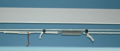
This may require some adjustment to get right. To answer the heading friction in this case is both friend and foe, as the spring requires friction, the motor does not. The motor with drive engaged is shown below.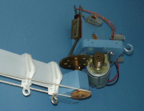
Depending on the length and weight of the curtains, the motor may have to be changed. I used a 12V hobby motor from Maplin electronics, I had to slightly enlarge the motor shaft with some brass tubing available from most hobby shops. The torque of the motor was not great, but if the output speed is reduced with gears, the torque (twisting force) is increased by the same amount. A worm gear has 1 tooth, and I used a 57 tooth gear, giving a reduction speed of 57:1. The torque of the motor (at the 57 tooth gear) is now increased 57 times. A light grease or machine oil may be applied to the gears, too much and it will splatter all over the walls and curtains!
Setting Up
This is best done with the curtains open, and motor gear unmeshed. Move one of the curtains by hand. They should move easily and meet in the centre of the rail, if not apply some silicone polish to the rail and alter the fastening on the wire.
Next switch the circuit to manual. With the curtains open, press the close switch. The curtains should start to close as long as the switch is pressed and stop moving when the switch is released. Then press the open switch. The curtains should now move as before but in the opposite direction. If all is well, open the curtains with the switch and then fully close them and use a watch to time this. The motor should be sufficiently slow and take a few seconds (about 3 in my case but my room is small).
Finally open the curtains, adjust the preset P1 to minimum resistance and set S3 to automatic. Press the close switch, the motor will run for a second or so and curtains will start to close. Switch back to manual and open the curtains, increase P1 slightly and switch back to auto and press close again. Repeat until the timing is sufficient for the curtains to close. Now press open (with S3 still in manual) the curtains should be timed to open fully.
Final Words
Should you have problems with this circuit, you first need to determine if its mechanical or electrical. Mechanical problems will happen on both manual and automatic settings, and be related to the opening or closing mechanism in general.
If electrical, check the power supply first, then L1 and L2 indications. If nothing works at all build the single manual relay circuit above and once perfected, return to the automatic version.
I am not mechanically minded so any suggestions or improvements towards a better mechanism can be included here; or if any of you have also made electric curtains, I will be happy to display your work.


